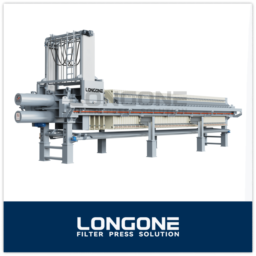
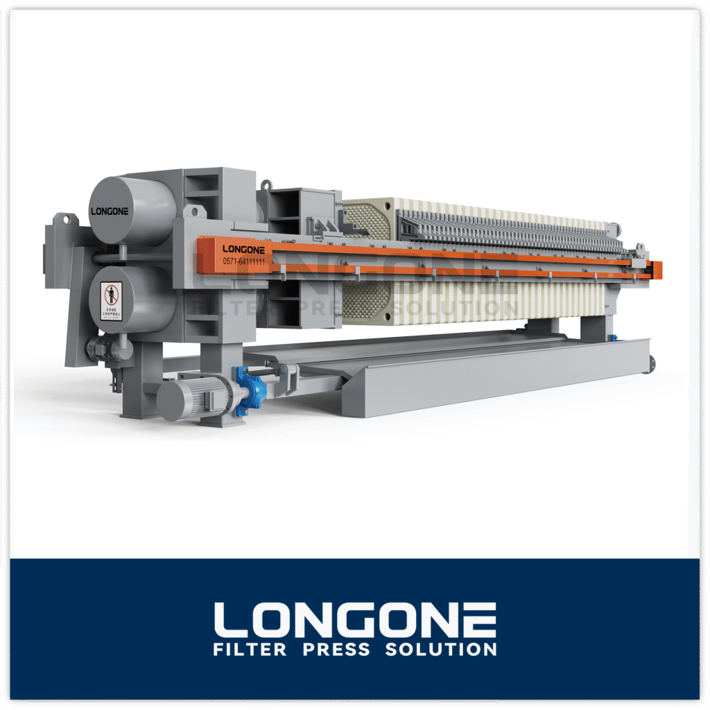
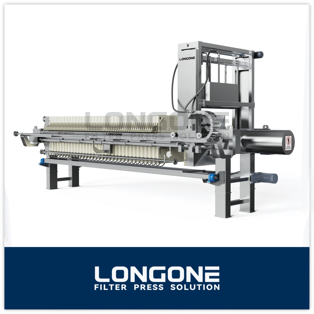
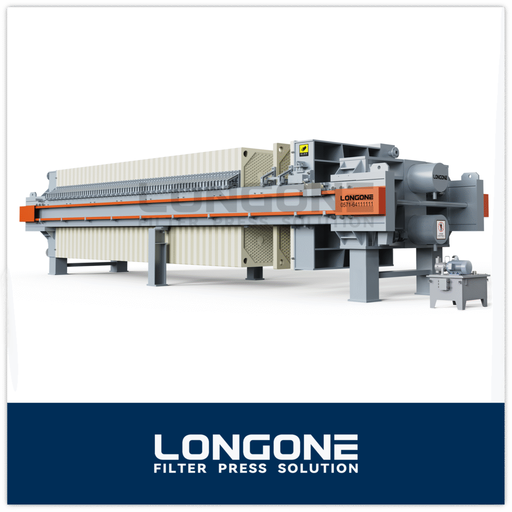
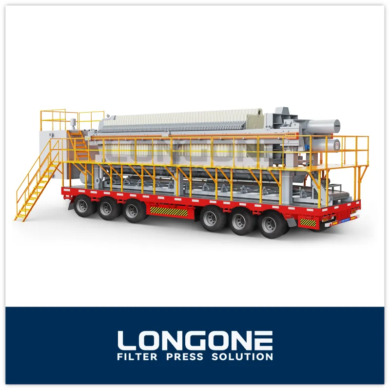
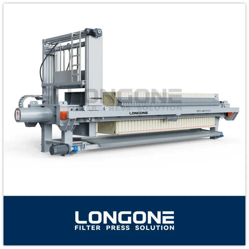
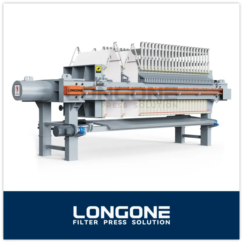
Two plate and frame filter press diagrams can look almost identical, yet the machines they describe can dewater very differently. A drawing shows layout. It does not show plate flatness, frame thickness, cloth choice or pressure rating, and those are the details that decide cake dryness, cycle time and leakage.
This guide walks through the diagram step by step: what each part does, how slurry moves through the stack, how open and closed discharge differ on paper, and which specifications you should confirm before you rely on any drawing to make a purchasing decision.
What Is a Plate and Frame Filter Press?
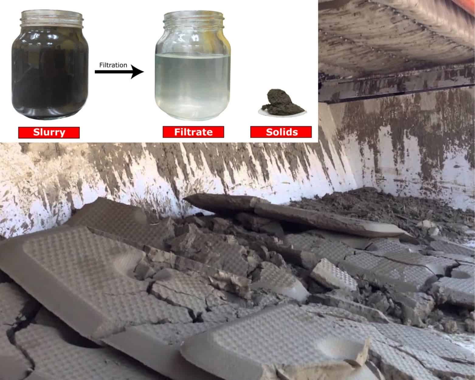
A plaat- en framefilterpers is a batch solid-liquid separation machine. It uses pressure to force slurry through filter cloth, which holds back the solids and lets the clear liquid (filtrate) pass through. The solids build up as a filter cake inside the machine, and the filtrate is collected and discharged.
What sets the plate and frame design apart is its structure. Solid plates and hollow frames are stacked in alternating order and pressed together between two end plates. The hollow frame forms the filtration chamber, and its thickness determines how thick the cake can grow. This differs from a recessed chamber press, where the chamber is molded into the face of each plate and no separate frames are needed.
Plate and frame presses are widely used where flexibility matters: laboratory and pilot work, fine chemicals, pharmaceuticals, food and beverage clarification, edible oils, and small-batch industrial slurries. They are valued for their simple construction, easy adjustment of cake thickness and straightforward maintenance.

Plate and Frame Filter Press Diagram: Main Components
A typical diagram shows the press from the side, with the frame assembly on the left and the closing mechanism on the right. The table below lists the parts you will see labeled and the role each one plays.
| Component | Function | Common materials |
|---|---|---|
| Head plate (fixed end) | Holds the stack in place; usually carries the slurry feed inlet | Cast iron, carbon steel, stainless steel |
| Tail plate (movable end) | Moves under closing force to compress the stack | Cast iron, carbon steel, stainless steel |
| Side beams (rails) | Support the plates and frames and guide their movement | Carbon steel, stainless steel |
| Filter plates | Support the cloth and provide drainage surfaces for filtrate | Polypropylene (PP), cast iron, stainless steel |
| Filter frames | Form the hollow chamber where cake builds up | Polypropylene (PP), cast iron, stainless steel |
| Filter cloth | Retains solids and passes filtrate | Polypropylene, polyester, nylon, others by application |
| Closing mechanism | Applies and holds clamping force | Hand screw, manual jack, or hydraulic cylinder |
| Feed and discharge ports | Route slurry in and filtrate out | Integral to plates and frames, or external piping |
Two small details on a good diagram are easy to miss. First, the plates and frames are usually shown with identification knobs (buttons) on their handles. These are not decoration. They help operators assemble the stack in the correct order, which matters most when washing plates are used. Second, the feed channel and filtrate channels should be drawn separately. If a diagram merges them into one arrow, it is oversimplified.
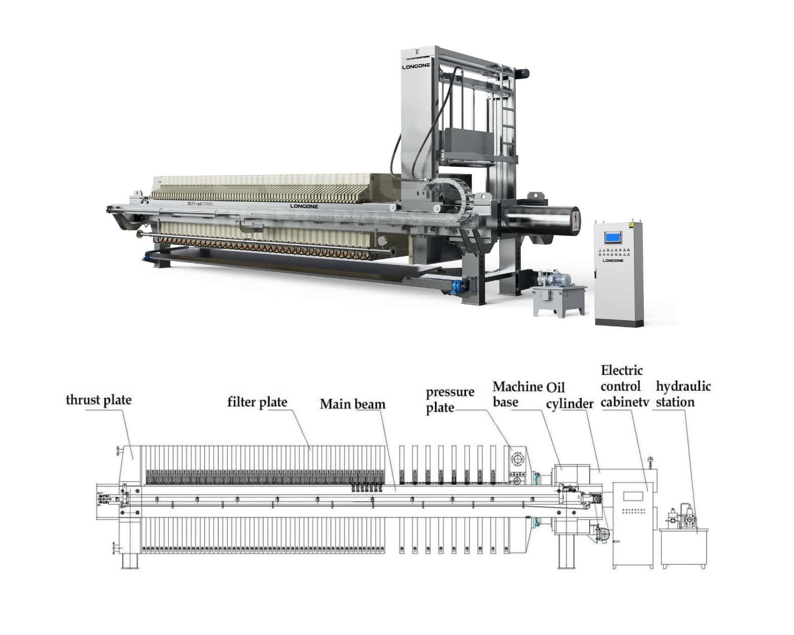
How the Plate and Frame Layout Works: Plates, Frames, Cloth and Feed Channels
Read the stack from the head plate to the tail plate and you will see a repeating pattern: plate, cloth, frame, cloth, plate, and so on. Each hollow frame is sandwiched between two cloth-covered plates. Together, those three elements make one filtration chamber.
Plates are not flat sheets. Their faces carry a pattern of studs, ribs or grooves that hold the cloth slightly off the plate body. This gap gives the filtrate somewhere to travel once it has passed through the cloth. If the drainage surface is blocked, damaged or poorly designed, filtrate cannot leave freely and dewatering suffers, even when everything else is correct.
Frames are open in the middle. Their thickness sets the cake thickness, which makes frame selection a real process decision. Thinner frames produce thinner cakes that dewater and wash more evenly. Thicker frames hold more solids per cycle but take longer to filter, and the cake core may stay wetter. Many buyers choose frame thickness based on how quickly the slurry blinds the cloth.
Filter cloth covers both faces of every plate. Its edges extend around the feed holes and act as a gasket, so a correctly fitted cloth contributes to sealing as well as filtration.
Feed channels are formed by aligned holes in the corners (or sometimes the center) of the plates and frames. When the stack is closed, these holes line up into a continuous channel. Small openings in the frame connect that channel to the chamber, so slurry enters the chamber from the side. Filtrate channels run through the plates, not the frames, which is why the two component types are not interchangeable.
A useful way to remember the layout: slurry flows into the frames, and filtrate flows out through the plates.

Filtration Flow Explained: From Slurry Feed to Cake Discharge
Once you understand the parts, the flow path on the diagram becomes easy to follow. A standard cycle has five stages.
- Closing. The closing mechanism pushes the tail plate toward the head plate and compresses the stack. Closing force must be high enough to keep the sealing surfaces tight under feed pressure.
- Feeding. A pump sends slurry through the feed inlet and along the feed channel. It enters each frame chamber through the feed opening.
- Filtration and cake formation. Pressure drives liquid through the filter cloth on both sides of the chamber. Solids stay behind and build up as cake against the cloth. The cake itself becomes part of the filter medium, which is why filtrate often runs clearer as the cycle progresses. Flow slows down as the cake thickens.
- Washing (optional). In a washing configuration, wash liquid is introduced through designated channels and passes through the cake to displace remaining filtrate or soluble impurities. This is where plate identification matters, because washing plates and non-washing plates alternate in a defined sequence.
- Opening and discharge. When flow drops to the target level, feeding stops, the press opens, and plates and frames are separated one by one so the cake can fall out or be scraped off. The cloth is inspected, cleaned if needed, and the stack is closed again.
Many plate and frame presses are operated manually or semi-manually, so the discharge step is labor-intensive compared with automatic chamber presses. That trade-off is often acceptable for small batches, frequent product changes and high-value products where flexibility is more important than throughput.
Closed vs Open Discharge Diagrams: Reading the Differences
Diagrams commonly show one of two filtrate discharge arrangements. They look similar at first, but they suit different applications.
Open discharge lets filtrate flow out of a tap or outlet at the bottom of each plate into a trough below. The operator can see the filtrate from every chamber. A cloudy stream points to a torn cloth or a poor seal on that specific plate, and the faulty plate can be isolated quickly. On a diagram, you will see individual outlets along the bottom of the stack.
Closed discharge routes filtrate through internal channels into a common discharge pipe, so it never touches open air. The diagram shows a manifold or a pipe connection on the head plate or at the side. This arrangement suits volatile, corrosive, hot or hazardous liquids, and it keeps the work area cleaner. The trade-off is reduced visibility: finding a faulty plate takes more effort.
The table below places plate and frame presses next to two other common designs so you can see where each fits.
| Feature | Plate and frame | Recessed chamber | Membrane (diaphragm) |
|---|---|---|---|
| Chamber formed by | Plate + separate frame | Recess molded into each plate | Recessed plate with flexible membrane |
| Dikte van de taart | Adjusted by frame thickness | Fixed by plate design | Fixed, then squeezed further |
| Typical operating pressure | Lower to moderate | Moderate to high | High, plus squeeze pressure |
| Cake dryness | Moderate | Goed | Highest |
| Automation level | Mostly manual or semi-automatic | Manual to fully automatic | Commonly semi to fully automatic |
| Meest geschikt voor | Small batches, clarification, flexible duty | General industrial dewatering | High-throughput, low-moisture cake targets |
If a supplier’s diagram does not make it clear which discharge style the machine uses, ask. It affects piping, operator safety and how you troubleshoot.

Reading a Filter Press Diagram Before You Buy: Specs That Matter
A diagram confirms the layout. It cannot confirm performance. Before you commit to a purchase, ask for the following information in writing.
- Plate and frame material. Polypropylene is common for general chemical resistance and lighter weight. Cast iron and stainless steel are chosen for higher temperature, higher pressure or specific process conditions. Match the material to your slurry’s pH, temperature and abrasiveness.
- Operating pressure rating. Confirm the maximum feed pressure the plates, frames and closing system are built for. Pressure capability varies with material and plate size, so do not assume it from the drawing.
- Filtration area and number of chambers. These determine batch capacity. Ask for the total filtration area and the cake volume per cycle.
- Frame thickness options. If your slurry characteristics may change, ask which frame thicknesses are available and whether they are interchangeable in the same press.
- Filter cloth specification. Material, weave, air permeability and micron rating strongly affect filtrate clarity and cake release. A cloth that suits one slurry can blind quickly on another.
- Sealing and plate flatness. Gasket surfaces and manufacturing tolerance determine whether the press seals under load. These cannot be seen on a drawing, so ask about quality checks and, where possible, request sample plates or factory inspection records.
- Closing system. Manual screw, mechanical jack or hydraulic: this decides operator effort, clamping consistency and the maximum practical size of the press.
- Discharge style and port locations. Confirm open or closed discharge, feed position (corner or center) and connection sizes so they match your piping.
A good supplier will answer these questions clearly and, if you share your slurry details (solids concentration, particle size, temperature, pH, target cake dryness), can suggest a suitable configuration instead of a generic one.

Veelgestelde vragen
What are the main parts of a plate and frame filter press?
The main parts are the head plate, tail plate, side beams, alternating filter plates and frames, filter cloth, a closing mechanism (manual or hydraulic), and the feed and discharge ports. The plates support the cloth and drain filtrate, while the frames form the chamber where cake builds up.
How does a plate and frame filter press work?
A pump feeds slurry into the chambers formed by the hollow frames. Pressure forces liquid through the filter cloth and out through channels in the plates, while solids collect as cake. When filtration slows down, the press is opened and the cake is discharged.
What is the difference between a plate and frame press and a recessed chamber press?
A plate and frame press uses separate hollow frames to form each chamber, so cake thickness is set by frame thickness. A recessed chamber press has the chamber molded into the plates themselves, which removes the frames and usually simplifies automation.
What is the difference between open and closed discharge?
With open discharge, filtrate flows from each plate into a trough where it can be inspected. With closed discharge, filtrate goes through internal channels into a common pipe. Closed discharge is better for hazardous or volatile liquids, while open discharge makes faulty plates easier to spot.
How do I choose the right plate material and size?
Start with your slurry’s temperature, pH and abrasiveness, then confirm the required filtration area and operating pressure. Polypropylene suits many general applications, while metal plates are used for higher temperature or pressure. A supplier can recommend a configuration if you provide your process data.
Conclusie
A plate and frame filter press diagram is a useful starting point. It shows how plates, frames and cloth are arranged, how slurry reaches the chambers, and where filtrate leaves the stack. Reading it correctly also helps you spot what the drawing leaves out: material grade, pressure rating, cloth specification and sealing quality.
Use the diagram to confirm the layout, then verify the specifications that determine real-world results. If you are comparing configurations or replacing worn plates, sharing your slurry data with a filter plate manufacturer early can save time and avoid costly mismatches. Our engineering team is happy to review your application and help you check that the press layout fits your process.